Background
One of the larger projects I am currently involved in is the development of a flexible, configurable and extensible communication protocol for Cairn devices. I will also be involved in its initial implementation in a product internally referred to as “The Octopus”, a configurable multi-laser laser bank. The project team consists of 4 other engineers and myself.
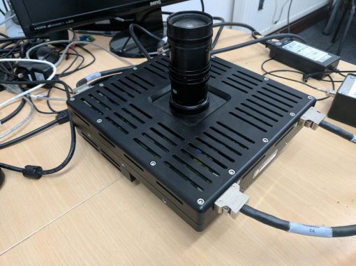
The Octopus consists of two separate modules contained in separate cases potentially places at quite a distance from one another. The first box is the laser bank itself, which contains all the optical hardware and the drive/feedback circuitry for the lasers. The second case contains the control and configuration circuitry and in future other processing modules which will extend the functionality of the system.
Project
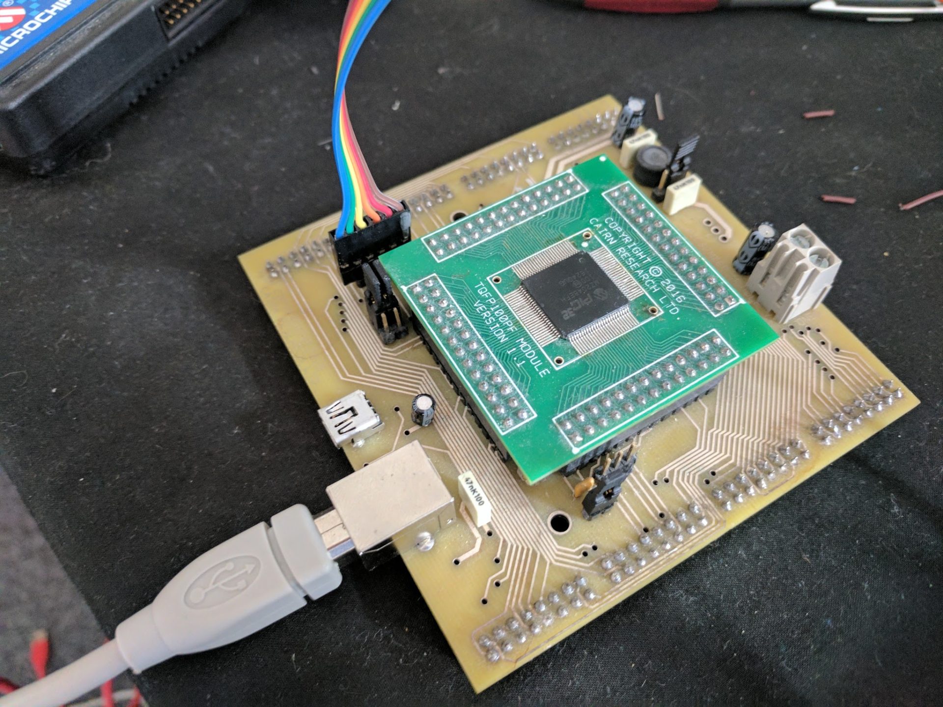
The possible long distance between the boxes and the potentially high noise environment of the laser bank itsself prohibits the use of simple TTL communication in this system. Before my arrival at Cairn the “Controller Area Network” (CAN) protocol was identified as a potential solution to the problem and shortly after my arrival I was asked to investigate it further. I quickly identified that it was suitable for Cairn’s needs and we began development of a generic board that would be capable of interfacing between Cairn devices over a CAN bus based on the PIC32MZ2048EFH100 microcontroller, manufactured by MicroChip.
The interface needs to be sufficiently generic that it is simple to allow it to control future Cairn devices and that it can be trivially integrated into new Cairn products if required. We decided that to fulfil these requirements a C library needed to be created for the PIC32 that would allocate certain GPIO pins to each device that requires communication with other devices on the CAN bus. This allows for two-way communication between the device and CAN interface, whilst allowing multiple devices to be connected to a single CAN interface. Upon receiving communication from a connected device, the interface will decide if it can respond itself, or if it needs to forward the message onto one of the other devices connected to it, or over the CAN bus. To simplify construction and allocation the controller allocates GPIO pins in blocks of 6 (3 digital and 3 analogue/digital pins). The pins in each block, the connected devices and the blocks allocated in each device will be flashed to ROM separately from the programming of the chip to allow them to be quickly reconfigured without code changes. This will require a piece of desktop software to be written to communicate this information to the interface over USB.
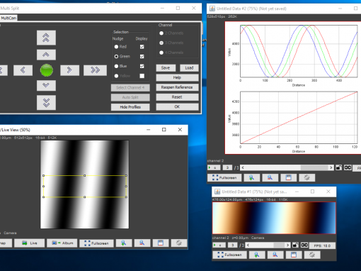
Currently the pin allocation and CAN communication software has been written for the PIC and the desktop software for configuring the interface is in development. Currently all of the microcontroller code has been written in ANSI-C (aka C89/90) for MicroChip’s XC32 compiler. The desktop software has been written in a combination of C# (due to the .NET framework’s simple SerialPort interface) and F# (due to having to parse certain C header files to get information about available pins and devices). Once this is finished I will also be designing the circuit board that allows the interface to connect to the Octopus.
Skills:
Teamwork
embedded C
C#
F#
electronics
Cairn Projects